Congratulations on your purchase of the Crest Revolution Train Engineer wireless control system. This product has been manufactured to the highest standards using only quality components and, with proper care, will provide you with reliable service. The Revolution TE operates on the 2.4Ghz frequency band for ultimate stability and interference free operation.
The Revolution TE lets you walk around your model railroad layout and remotely control your locomotive speed, direction, lights, sounds, and smoke from up to 400 feet away. The Revolution TE was developed to provide the model train enthusiast with complete integrated control of their dream layout, without the need for complicated layout wiring or complex control panels.
The Revolution TE receiver is designed to operate between 12 to 24 volts applied either to the track or from on board batteries. The Receiver is designed for “plug and play” installation in any Aristo-Craft Locomotive with a DCC/RCC board. The receiver can also be installed in any large scale locomotive with the use of a supplied Adaptor Plug. General instructions for custom installations are included in this manual.
OPERATION OVERVIEWBefore you start working with the Revolution TE there are a few concepts that you need to understand.
The transmitter and the receivers in your locomotives are designed to communicate and exchange information about the way you want your trains to operate. In order to
establish a link between them you need to set up some basic parameters that denethe locomotive for the Transmitter such as the locomotive’s name and road number. Once these parameters are set, the link between the transmitter and receiver is
nalized by a process called “Linking”. Once linked, the transmitter and receiver are set to communicate and run your train. As you get comfortable with the Revolution TE, you can start ne tuning the optional settings for each locomotive. These optionsinclude setting the top speed that you want a locomotive to achieve, the rate at which you want it to accelerate, how long you want it to delay when the direction is changed, headlight operation and many more.
The second concept has to do with the Cab Assignment. Once you link a locomotive receiver to a transmitter you must set the Cab Number that the locomotive will run under. Cab Numbers range from CAB-0 through CAB49. This allows you to easily move between as many as 50 Single Unit locomotives and Multiple Unit Consists while operating your model railroad. CAB-0, CAB-1 and CAB-2 might be used to operate three different locomotives while CAB-3 can be used to operate those same three locomotives in a consist. Changing between Single Unit (SU) operation and Multiple Unit (MU) operation is as simple as selecting a Cab Number.
Once you have an opportunity to experience the process used to operate trains with the Revolution TE you will nd that Aristo-Craft has found an elegant, easy to understand solution, to what can be a complex problem.

Spread spectrum radio transmission provides immunity from other radio sources • Range exceeds 400 feet outdoors and 300 feet indoors. • Continuous bidirectional 2.4Ghz communication between transmitter and • receiver for smooth operation and operator feedback.
The active locomotive is shown on a graphical, backlit, LCD display The receiver automatically shuts down if overload or overheating occurs -
The error that causes a locomotive shut down is displayed on LCD display Locomotives are identified by name and road number • Up to 6 locomotives can be linked together (MUed) into a consist • Up to 10 MU consists can be setup and controlled by one transmitter • Locomotives can be added or removed from an MU consist without relinking •
TRANSMITTER FEATURES:Large LCD graphic screen, backlit for night operation • One handed operation • Intuitive, simple data input is entered using cell phone style texting techniques • Memory For Up To 50 Unique Locomotives On Each Transmitter • Multiple transmitters can operate without interference with one another • Simultaneous Single Unit ‘SU’ and Multiple Unit ‘MU’ operation • All Stop Key to provide an emergency stop for all trains on a transmitter •
RECEIVER FEATURES:Plug and play installation in most Aristo-Craft locomotives • On-board battery or track power • Six auxiliary outputs on the receiver to control sound, smoke and lights • 5 Amps continuous power with peak loads up to 8 amps • Polarity protection • Overload protection •
INDIVIDUALIZED LOCOMOTIVE PROGRAMMABLE SETTINGS:Programmable momentum control and forward & reverse delay • Adjustable start speed • Adjustable top speed • Direction control headlights • Direction control motor setting for MUing locomotives back-to-back. • Function key assignment for • six auxiliary outputs Copy locomotive settings for fast replication of similar locomotives •
ADDITIONAL EQUIPMENT AVAILABLE SEPARATELY:CRE57001 Revolution TE Transmitter • CRE57002 Revolution TE Receiver • CRE57073 Smoke Control Board • CRE57076 Capacitor Board • CRE57080 TX Battery NI-Cd Battery & Charger • CRE57072 Transmitter Battery Charger (without batteries) •
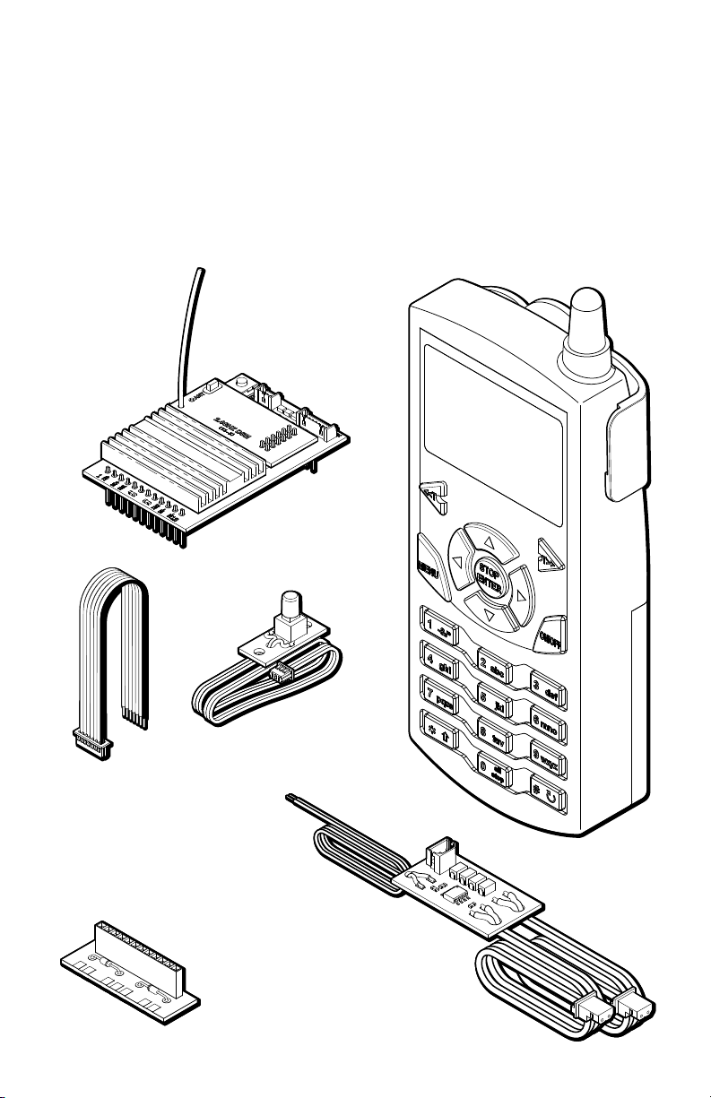
CRE57002 Receiver which includes a Remote Link Switch, an Auxiliary • Control Harness and an Adaptor Plug
CRE57073 Smoke Control Board. •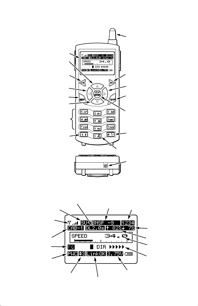
CRE57002 Revolution TE 2.4 Ghz Receiver • REMOTE Link Switch • Phillips head screwdriver • A drill and drill bits to install the remote Link Switch (if desired) •
NOTE: If the locomotive does not have a DCC/RCC compatible main circuit board, see the custom installation instructions beginning on page 31 of this manual.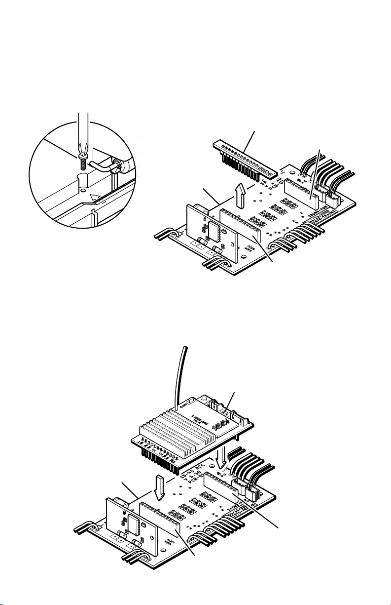
to determine where the DCC/RCC socket is located. Turn the locomotive (or tender) over, and remove all screws that hold the shell to the frame. Depending on the model of the locomotive, the number of screws will vary.
2) Remove the jumper plug on the DCC/RCC socket and set it aside. You can restore the locomotive to its pre-installation state by reinstalling the jumper plug.
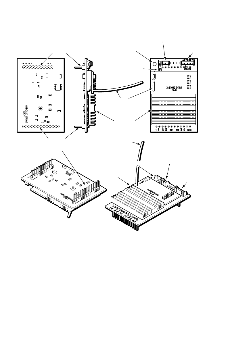
3) Install the receiver in the 12 pin DCC/RCC socket and the 10 pin support socket as shown making sure to match the 12 pin header to the 12 pin socket and the 10 pin header to the 10 pin socket.
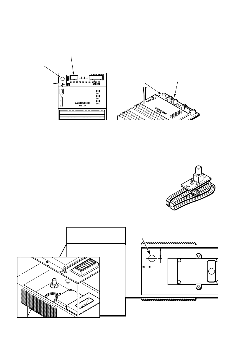
accessible from the outside of the locomotive, yet obscured from view. Under a removable hatch or through the bottom of the locomotive or tender are convenient locations, in most cases. The Remote Link Switch must not be mounted on a metal or conductive surface since this may cause a short circuit.
A typical installation in the Aristo-Craft SD45 is shown below. Drill a 5/16”(8MM) diameter hole in the selectedlocation. Install the Remote Link Switch through the hole from inside and secure it with hot melt glue or silicone adhesive.
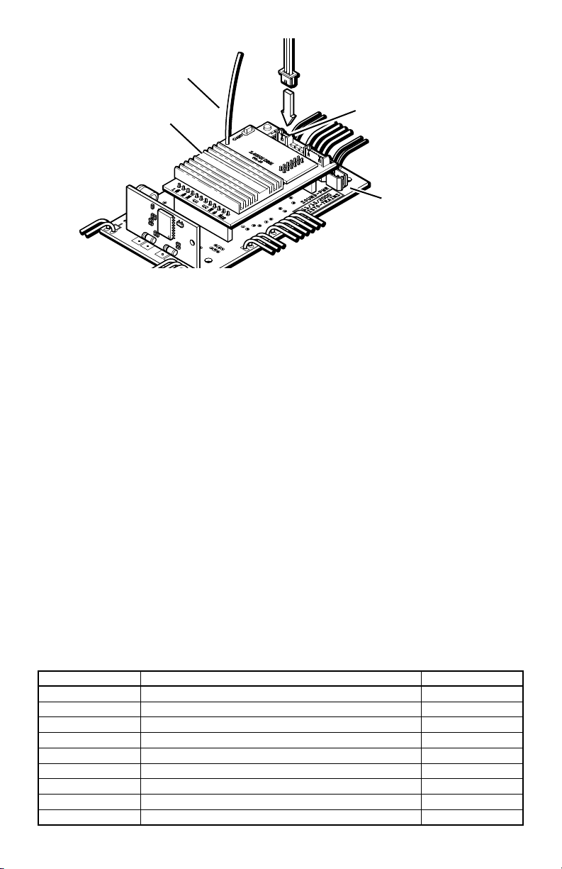
5) Attach the remote link switch connector on the Remote Link Switch to the three pin header on the receiver as shown on the following page.
6) Reinstall the locomotive shell. Use care when reassembling the locomotive. Be careful that you do not pinch any wires between the shell and internal parts of the locomotive.
THIS COMPLETES BASIC INSTALLATION OF THE RECEIVER. After the Transmitter set-up is complete, you will have full remote control of your locomotive speed, direction and lights. If you wish to add advanced options such as remote operation of smoke and sound please refer to the advanced section later in this manual.
POWERING YOUR LOCOMOTIVESTRACK POWER. The Revolution TE receiver will work on voltages ranging from 12 to 24 volts DC. When running from track power, connect DC power directly to the track and set your controller power to the highest setting, but not more than 24 volts. You can also connect a DC power supply of up to 24 volts, without any speed controller, directly to the track. Set the track/battery switch on your locomotive to ‘Track’.
BATTERY POWER. The Revolution TE receiver can also be powered from Li-Ion (Lithium Ion), Ni-MH (Nickel Metal Hydride), Ni-Cd (Nickel Cadmium) or Gel Cell batteries. The maximum voltage must not exceed 24 volts. Multiple batteries can be wired in series or parallel to increase voltage or run time. When operating from batteries, set the track/battery switch on your locomotive to ‘Battery’. The following batteries and cables are available from Aristo-Craft dealers.
PART NUMBER DESCRIPTION CHARGERCRE55610 Li-Ion, 2 AMP - 21.5 Volts CRE55620 CRE55650 Ni-MH 2.8 AMP - 12 Volts CRE55660 CRE55653 Ni-MH 2.8 AMP - 19.2 Volts CRE55661 CRE57080 Ni-Cd 1.5 AMP - 12 Volts CRE55660 CRE55493 Gel Cell 3.2 AMP - 3 X 6V CRE55494 CRE55601 Auto Cutoff For Gell Cell Battery CRE55602 Wire Harness For Battery Set CRE55611 Y Plug In Parallel CRE55613 Y Plug in Series